March 15, 1949. J. M. HILBORN SERVICE 'RIBBON BAR Filed sept. 2s. 1944 INVENTOR JEROME M H/LBORN i I i ATTORNEY Patented Mar. 15, 1949 SERVICE RIBBON BAR Jerome M. Hilborn, Bronxvlle, N. Y., assignor to Hilborn-Hamburger, Inc., New York, N. Y., a corporation of New York Application September 23, 1944, Serial No. 555,550
(Cl. Ll--1.5)
4 Claims.
This invention relates to service ribbon bars.
An object of this invention is to provide a service ribbon bar of the character described having highly improved Vmeans for clamping the ribbon to the bar, said clamping means being so constructed that the ribbon can easily be removed .or replaced.
Still a further object of this invention is to provide a compact, neat and durable service ribbon bar of the character described, which shall be relatively inexpensive to manufacture, easy to attach to a garment, and which shall yet be lattractive in appearance, and practical and eicient to a high degree.
The invention accordingly consists in the features of construction, combinations of elements, and arrangement of parts which will be exemplified in the construction hereinafter described, and of which the scope of application will be indicated .in the following claims.
In the accompanying drawing, in which is shown various possible illustrative embodiments of this invention:
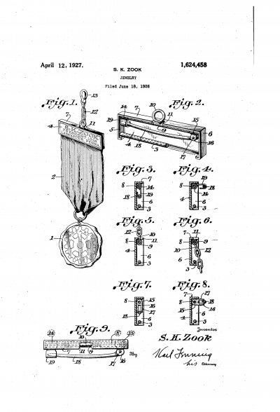
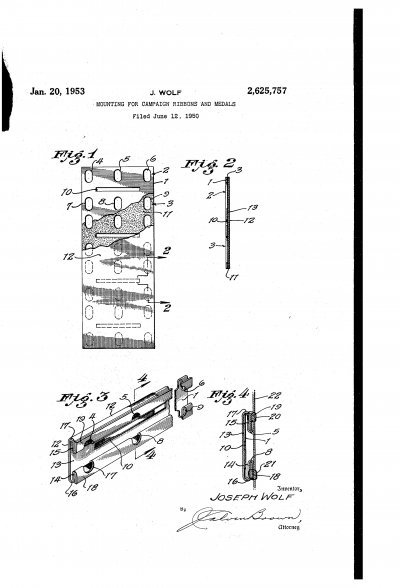
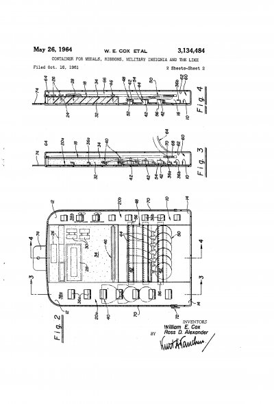
Fig. 1 is a front elevational view of a service ribbon bar embodying the invention.
`forming part of the service ribbon bar shown in Fig. 1.
Fig. 4 is :a perspective view of the clamp plate forming part of the service ribbon bar shown in Fig. 1.
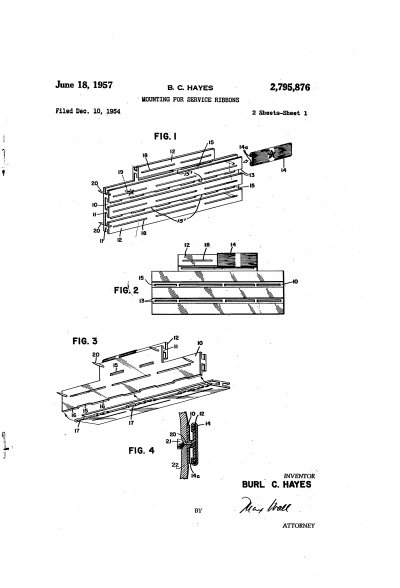
Fig. 5 is a front elevational view of a service ribbon bar embodying the invention as utilized for supporting a plurality of individual ribbons.
Fig. 6 is a top edge View thereof.
Fig. 7 is a rear view thereof.
Fig. 8 is a rear view of three separate ribbon holders end to end, which may be mounted on a single service clamp plate.
Fig. 9 is a rear view of the plate clamp forming part of the service ribbon bar shown in Fig. 5.
Referring now in detail to the drawing, ID designates a service ribbon bar embodying the invention. The same comprises a ribbon holder II on which the service ribbon I2 is mounted, and a 2 clamp plate I3 for clamping the ribbon to the ribbon holder.
The ribbon holder II may be made of sheet metal, and comprises a channel-shaped member having a web I5 and parallel top and bottom anges I6. The web I5 may be formed with a cutout or opening I'I to reduce its weight, and flanges I6 are formed with aligned, narrow, longitudinal, central slots I8 adjacent the web I5. The slots I8 are short relative to the length of the holder II :as shown in Fig. 3 oi' the drawing. The ribbon I2 has a portion Iza covering the front surface of web I5, portions |2b covering the outer surface of flanges I6, portions I2C covering the inner surfaces of flanges I6, and portions |2d contacting part of the inner surface of the web I5, The holder Il is of substantially the same length as the width of the ribbon and, as shown in Fig. 2 of the drawing, the ribbon is drawn around the edges Ia of anges I6.
The service ribbon is clamped in place on the holder I I by means of the clamp plate I3. Said plate may also be made of sheet metal. It is substantially rectangular in shape and adapted to iit into the channel-shaped holder Il. Clamp plate i3 is substantially as long as holder II and may be formed with ay central cutout or opening 20 to reduce its weight. It is furthermore formed with a pair of outwardly projecting, central lugs 2| on the upper and lower longitudinal edges |3a thereof. The width of the plate I3 is such as to nicely fit within the holder, allowing for the thickness of the ribbon, and engage the service rib-bon to hold portions |20 of the ribbon against the inner surfaces of the flanges I5.
The clamp plate also holds portions |2d of the service ribbon against the inner surface of web I5; the projections or lugs 2| bulge portions of the ribbon into slots I8, thereby rmly clamping the ribbon in taut condition on the ribbon holder II. The clamp plate I3 may be provided with a pivoted attaching pin 25 for pinning the bar Ill to a garment. Any other suitable means may be provided on clamping plate I3 to attach the bar to a garment.
In Figs. 5 to 9, there is shown a service bar pin Illa embodying the invention and illustrating a modified construction. The bar pin Illa is for mounting a plurality of ribbons in tandem. The bar pin Illa comprises an elongated clamp plate 30, the length of which is a multiple of the length of a single ribbon; thus, it may be either two, three or four times as long as a single clamp plate I3. It may be formed with a plurality of longitudinal slots 3|, each one centralized with ment.
respect to the length of a single ribbon. The clamp plate 30 is also formed in the upper and lower edges thereof with outwardly projecting pairs of lugs 32 centralized relative to the slots 3|. Fitted on the plate 30 are a plurality of holders l! in tandem, with ribbons l2 thereon. Thus in the drawing, the service ribbon bar Illa is for mounting three ribbons, and hence three ribbon holders, each with a ribbon thereon, may be mounted on the one clamp plate. The ribbon holders are separately removable for replacing the ribbons.
The clamp plate 39 may be provided with any suitable means for attaching the same to a gar- In the drawing, plate 39 is shown to be provided at the ends thereof with rearwardly projecting pins 35 which may pierce the garment and receive pin locks thereon. It will be noted that each pair of projections 32 may bulge a ribbon into a pair of slots I8 on one of the ribbon holders Il.
To remove a ribbon holder, it is but necessary to press up on one flange I6 of the holder, and swing the holder out about its lower flange. The flanges are resilient and hence removal or mounting of the holders is easily accomplished.
It will thus be seen that there is provided a device in which the several objects of this invention are achieved, and which is well adapted to meet the conditions of practical use.
As various possible embodiments might be made vof the above invention, and as various changes might be made in the embodiments above set forth, it is to be understood that all matter herein set forth or shown in the accompanying drawing is to be interpreted as illustrative and not in a limiting sense.
Having thus described my invention, what I claim as new and desire to secure by Letters Patent, ist
1. A service ribbon bar comprising a channel- `shaped ribbon holder having a web portion and parallel anges extending substantially at right angles from said web portion, said flanges being formed with openings, and a clamp plate removably fitted between said flanges, and formed with projections adapted to urge into said openings portions of ribbon on said ribbon holder, said holder being of substantially the same length as saidclamp plate, and means on the clamp plate for attaching the same to a garment.
2. In combination, a channel-shaped ribbon holder having a web portion, and parallel flanges extending substantially at right angles from said web portion, said anges being formed with openings, a ribbon contacting the outer surface of the `web and being folded over the outer surfaces of the flanges and around the edges of the flanges and contacting the inner surfaces of said flanges and the inner surface of said web, and a remov- .6 able clamp plate within said ribbon holder, and
Number Name Date 562,828 House et al June 30, 1896 592,610 Hornich Oct. 26 1897 1,235,580 McDougall Aug. 7, 1917 '50 1,413,468 Gaunt Apr. 18 1922 1,490,624 Mitchel Apr. 15, 1924 1,511,093 Pfeiferle Oct. 7, 1924 1,450,722 Gaunt Apr. 3, 1923 1,852,165 Jabelonsky Apr. 5, 1932 .55 2,125,699 Updike Aug. 2, 1938 2,355,546 Michaels Aug. 8, 1944 2,413,056 Levyn Dec. 24, 1946 FOREIGN PATENTS 0 Number Country Date 135,430 Great Britain Nov. 27, 1919 between the flanges thereof, said clamp plate having projections on the longitudinal edges thereof pressing portions of the ribbon into the openings in said flanges.
3. In combination, a channel-shaped ribbon holder having a web portion, and parallel flanges extending substantially at right angles from said web portion, said flanges being formed with openings, a ribbon contacting the outer surface of the web and being folded over the outer surfaces of the flanges and around the edges of the flanges and contacting the inner surfaces of said flanges and the inner surface of said web, a removable `clamp plate within said ribbon holder, and between the flanges thereof, said clamp plate having projections on the `longitudinal edges thereof pressing portions of the ribbon into the openings in said flanges, said openings being located adjacent the web portion of the holder, and said clamp plate being adapted to press portions of the ribbon against the inner lsurface of the web, and against the inner surfaces of said anges.
4. A multiple service ribbon bar comprising an elongated clamp plate having on its longitudinal edges spaced pairs of opposite projections, ribbon holders removably secured on said clamp plate in tandem, said ribbon holders each being channel shaped, and having a web portion and yielding parallel anges extending substantially at right angles from said web portion, said flanges being formed with longitudinal slots adjacent the web, each pair of lugs on the clamp plate 4projecting into a pair of slots in one of the holders, and a ribbon on each holder covering the front face of the web and folded around the flanges and contacting the inner surface of the web, and said lug serving to press portions of the ribbon into said slots.
JEROME M. HILBORN.